
- Product -
Product Introduction:High-voltageshuntcapacitor selectionsampleXian HuachaoPowerGroupCo.LTDXIANHUACHAO POWER CAPACITOR CO.,LTDBAM(AAM)Highvoltageparallel(filter)capacitor1 Product UseThisproductissuitablefor50Hzfrequencypowersystem,mainlyusedtocompensate the rea……


High-voltage shunt
capacitor selection sample

Xi 'an Huachao Power Group Co. LTD
XI'ANHUACHAO POWER CAPACITOR CO.,LTD
BAM (AAM) High voltage parallel (filter) capacitor
1 Product Use
This product is suitable for 50Hz frequency power system, mainly used to compensate the reactive power of the power system, improve the load power factor, reduce the reactive power transmission of the line, improve the transmission capacity of the grid, reduce power loss, reduce energy loss, improve voltage quality and improve equipment utilization. Mainly for chemical industry, steel mill, aluminum factory, cement factory, non-ferrous metal industry and other
fields.
2 Product advantages
Xi 'an Hua ultra-high voltage parallel (filter) capacitor has excellent performance, reliable quality, low loss and short production cycle. The production of capacitors strictly implements the International Electrotechnical Commission standard IEC 60871-2005, the national standard GB/T 11024-2019 and the power industry standard DL/T 840-2006. The product performance meets or exceeds the
standard requirements.
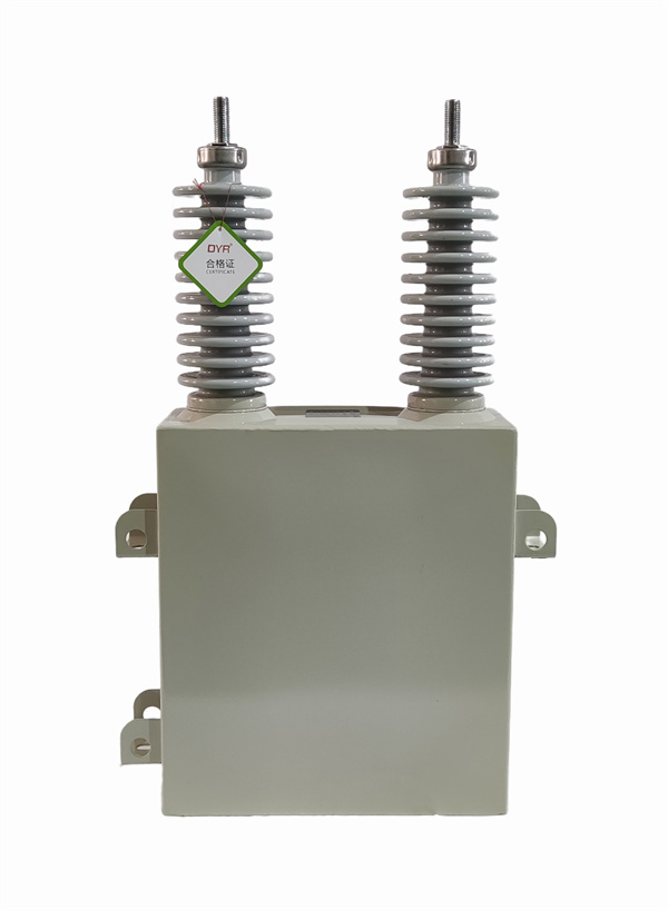
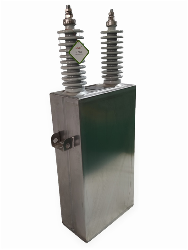
3 Product structure
The product is made of coarse polypropylene film and benzyl toluene as the medium, aluminum foil for electronic and power capacitors as the electrode, and non-
inductive coil method is adopted.
3.2 The shell is made of stainless steel plate sealed by argon arc welding. The flexibility of the housing is used for oil compensation. Hanging clamps are welded on both sides of the shell box wall for handling and installation. The cover of the shell is provided with an outlet sleeve, which is made of rolled porcelain
sleeve. It has good sealing performance.
4 Product process
4.1 Convex foil non-inductive winding method, starting, ending and leaving edge
folding process.
All the residual water and air in the capacitor are removed by the single pump single injection high vacuum dry impregnation technology, and the low temperature impregnation agent is filled. The impregnating agent has excellent low temperature
performance and partial discharge performance.
4.3 Shell surface spraying paint: beautiful appearance, strong adhesion, effective
sunscreen, rain proof.
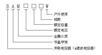
5 Product model and meaning
6 Technical parameters
6.1 Main Parameters
6.1.1 Rated frequency: 50Hz.
6.1.2 Test voltage between terminals: AC test voltage 2.15UN or DC test voltage
4.3UN, lasting 10S.
6.1.3 Loss Angle tangent value (tanδ) : less than 0.0005.
6.1.4 Number of phases: single or three phase.
6.1.5 Insulation level: The high voltage terminal of the capacitor should be able
to withstand 42kVac test voltage between the ground and the time is 1min.
6.1.6 Discharge resistance: The capacitor is equipped with internal discharge resistance, and after disconnecting from the power grid, the voltage on the terminal can be reduced to less than 75V within 10 minutes. If you have any
special requirements, please put forward when ordering.
6.1.7 Capacitance deviation: The difference between the measured capacitance value of the capacitor and the rated value shall not exceed -5% ~ +5% of the rated
value.
6.1.8 The ratio of maximum capacitance to minimum capacitance between any two
terminals of a three-phase capacitor shall not be greater than 1.02.
6.1.9 Execution standard:
IEC60871-2005 "Shunt Capacitors for AC power systems with nominal voltage
above 1kV"
GB/11024-2019 "Shunt capacitors for AC power systems with nominal voltage
above 1kV"
DL/T840-2006 "Technical Conditions for Use of High voltage Shunt Capacitors"
6.2 Overload
6.2.1 Capacitors can operate at the voltage levels shown in Table 1.
Table 1

6.2.2 Operate the overvoltage
The remaining voltage on the capacitor before it is put into operation should not exceed 10% of the rated voltage. Fitting a capacitor bank with a nondisruptive
circuit breaker will usually produce a first transition voltage with a peak value
of no more than 2 √2 times the applied voltage (square mean root value) and a duration of no more than 1/2 cycles. Under these conditions, capacitors can fit 1000 times per year (corresponding peak transition overcurrent up to 100 IN). Where the capacitor is met more frequently, the amplitude and duration of the overvoltage as well as the transition overcurrent should be limited to a lower
level, the limits of which should be negotiated and stated in the contract.
6.2.3 Maximum allowable overcurrent
The capacitor unit shall be suitable for continuous operation under the current generated by the unit at rated sinusoidal voltage and rated frequency at the root value of the current square of 1.3 times, except for the transition process. Since the actual capacitance can reach a maximum of 1.05CN, the maximum
solid current can reach 1.365IN.
6.2.4 Power frequency plus harmonic overvoltage
The addition of harmonic overvoltage to the power frequency during the operation of the capacitor shall not cause the overcurrent to exceed the current value specified in Article 6.2.3. If the capacitor is operated for a long time at no higher than 1.1UN, the peak voltage including all harmonic components should not exceed 1.2 √2UN. If you have any special requirements please make them at the
time of ordering.
7 Conditions of Use
7.1 Indoor or outdoor installation for use.
7.2 The elevation of the installation site is less than 1000m (for areas higher
than 1000m, please use plateau capacitors).
7.3 Temperature category: -40/D.
7.4 The remaining voltage shall not exceed 10% of the rated voltage.
7.5 There is no gas or steam that is seriously corrosive to the metal.
7.6 No strong mechanical vibration.
7.7 No explosion or flammable materials.
7.8 The harmonic content of the installation site shall meet the requirements of
relevant national standards, and if there are special requirements, it shall be
indicated in the contract.
7.9 The switching switch should have no re-breakdown.
8 Transport and store
8.1 Hoisting and transportation precautions:
8.1.1 The capacitor must be packed in the packing box before transportation, but the capacitor can also be installed in the cabinet for transportation under the condition that the connection bolt is not loose and the capacitor is not distorted by a large impact, but the connection line must be removed.
8.1.2 The capacitor should be in the upright position when handling, that is, the
sleeve is upward. It is strictly forbidden to carry the sleeve.
8.1.3 When hoisting capacitors, attention should be paid to avoid collision and friction, care should be paid to avoid damage to the casing, and special attention
should be paid to the possible damage to the capacitor during hoisting.
8.2 Storage Conditions and Precautions:
8.2.1 There should be no direct heat source and no corrosive gas in the storage
area.
8.2.2 When capacitors are stored, it is not allowed to place one capacitor directly
on top of another capacitor without support.
9 Acceptance
9.1 Technical data to be provided before delivery
9.1.1 Shipping list.
9.1.2 Inspection report.
9.1.3 Certificate of qualification.
9.2 After receiving the capacitor, the user should first carry out an appearance
inspection to check the correctness of the shell, porcelain sleeve, outlet guide
bar and nameplate, and check whether the capacitor is leaking oil.
9.3 When conditions permit, the following tests are recommended.
9.3.1 Measuring capacitance with a relative error of no more than 3%, should be
consistent with the nameplate and test report value or tend to be consistent.
9.3.2 When the pole to the shell power frequency withstand voltage test, the applied voltage is 75% of the factory test voltage or lower, and the time is 1min. 9.4 If you have any questions during acceptance, please contact the sales
department of the company.
10 Installation
10.1 Ventilation should be good for indoor use. When installing outdoors, try to make the small side of the capacitor face the direction of the direct sun for a
long time.
10.2 Capacitors can be installed on the frame, in order to ensure good ventilation, the spacing of each layer of capacitors should not be less than 50mm. Row spacing should not be less than 150mm. Capacitor bottom distance from the ground indoor products should not be less than 200mm, outdoor products should not be less than 300mm. The net distance from the bottom of the device to the roof should not be
less than 1000mm.
10.3 The electrical connection of the capacitor must use a soft connection. The connection should be made by clamping two wrenches up and down, and the tightening torque should not be greater than 52N·m. Capacitors should be arranged so that
the nameplate is outwards, so as to facilitate staff inspection.
10.4 The housing potential must be fixed when capacitors are mounted on insulated
brackets.
When the capacitor housing is grounded, the grounding part should be kept in good
contact.
11 Precautions for capacitor
11.1 High voltage fuses for external protection of high voltage shunt capacitors are recommended. 11.2 The capacitor bank should be equipped with internal fault, over current, over voltage, loss of
voltage and other protection.
11.3 When the voltage on the bus bar exceeds the maximum allowable value specified in the overload
(article 6.2.1), the capacitor bank shall not be connected to the network.
11.4 The capacitor bankshall not be re-connected to the network within 10min after it is disconnected
from the network.
11.5 The discharge of the capacitor bank shall be automatic each time it is disconnected from the
network.
11.6 Before contacting the conductive part of the capacitor disconnected from the network, even if the capacitor has discharged automatically, the outlet end of the capacitor must be short-circuited and
connected to the ground wire for individual discharge.
12 Maintenance and
12.1 Routine maintenance and maintenance:
12.1.1 The capacitor room should have staff or equipment on duty to record the operation in detail. 12.1.2 It is recommended to check the appearance of the capacitor every day. For example, the
capacitor should be free of leaking oil and the joint is heated.
12.1.3 The temperature of the capacitor installation site should be recorded.
12.2 Check regularly
Regular inspection of capacitors can generally be carried out once a year, and capacitors operating under special conditions can shorten the inspection cycle appropriately according to the specific
circumstances. The specific contents of the inspection are as follows:
12.2.1 Measure the capacitance of the capacitor and compare with the previous record. If there is a significant change, promptly replace with the same specifications of the product. Check whether the capacitor is leaking oil, whether it has been polluted, if there is dirt should be cleaned up. Such as:
capacitor sleeve surface, capacitor shell and mounting bracket, etc.
12.2.2 Check regularly whether the contact of all electrical connection points is good. If there is an
accident, it should be dealt with in time to avoid accidents.
13 Repair and replace
13.1 The following faults can be repaired by the user at the installation site.
13.1.1 Slight leakage of oil above the case shell can be repaired by solder sealing or oil surface repair
glue.
The leakage of oil in the weld can be repaired by plugging glue.
Under the following circumstances, the capacitor should be considered for replacement:
13.2.1 The capacitance change of the capacitor exceeds 6% of the nameplate value.
13.2.2. Short-circuit fault to ground.
13.2.3 The insulation resistance to the ground is less than 2000 megohm.
13.2.4 Capacitor bushing cracks or bursts.
13.2.5 The capacitor casing is bulging or bursting.
13.2.6 Serious leakage of oil has occurred in the capacitor.
13.2.7 Capacitor service life is more than 10 years.
14 0peration site


35kV substation of Henan Yichuan Electric Power Company


80Mkvar electric arc furnace compensation project operated by Yonggang
Group


Second Automobile Shenlong Automobile Chengdu 24Mvar reactive
power compensation project
15 Volume table
High voltage shunt capacitor volume table


Note: 1. Capacitors with rated voltage of 12kV and below can be
supplied with single or double bushing.
2. Capacitors with rated voltage of 12kV and above are
generally single bushing.
3. Capacitor units above 400kvar are available on request with
2 or 3 lifts.
4. Different product specifications, the selection of sleeve is different, (generally 6kV system uses 6 umbrella porcelain sleeve,
10kV system uses 10 umbrella porcelain sleeve)
5. Filter capacitor unit products need to be customized
according to specific projects.
16 Drawings
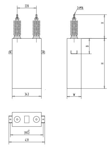
Outline diagram of a shunt capacitor

top
 Scan to follow
$citylist

 current location:


